Communication System
October 31, 2016
Categorised in: Data Communicaiton & Wireless Sensor Networks
DATA COMMUNICATION
Data communications are the exchange of data between two devices via some form of transmission medium such as a wire cable.
Characteristics
- Must be a Sender and Receiver
- A protocol is a set of rules which governs the transfer of data between computers. Protocols allow communication between computers and networks.
- Handshaking is used to establish which protocols to use. Handshaking controls the flow of data between computers
- Protocols will determine the speed of transmission, error checking method, size of bytes, and whether synchronous or asynchronous
- Examples of protocols are: token ring, CSMA/CD, X.25, TCP/IP
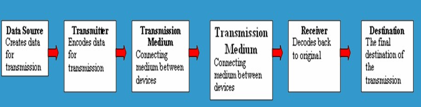
Every communication system has 5 basic requirements:
- Data Source (where the data originates)
- Transmitter (device used to transmit data)
- Transmission Medium (cables or non cable)
- Receiver (device used to receive data)
- Destination (where the data will be placed)

TRANSMISSION MEDIA SPEED
- Bandwidth: The amount of data which can be transmitted on a medium over a fixed amount of time (second). It is measured on Bits per Second or Baud.
- Bits per Second (bps): A measure of transmission speed. The number of bits (0 0r 1) which can be transmitted in a second
- Baud Rate: Is a measure of how fast a change of state occurs (i.e. a change from 0 to 1)
Any transmission may be:
- Analog or Digital
- Serial or Parallel
Serial Transmission
Data is transmitted, on a single channel, one bit at a time one after another
– Much faster than parallel because of way bits processed (e.g. USB and SATA drives)
Parallel Transmission
Each bit has it’s own piece of wire along which it travels
Often used to send data to a printer
Why Not use Parallel Instead of serial?
- Due to inconsistencies on channels data arrives at different times
- Because of the way it is transmitted packet switching cannot be used
- The above two points makes parallel slower than serial and requires higher bandwidth.
- Parallel transmissions are rarely used anymore
Transmission Modes
Simplex: One direction only
Half duplex: Both directions but only one direction at a time
Full duplex: Send and receive both directions at once


PULSE MODULATION

Analog to Digital Conversion
- Modulation is efficient transmission of signal over channel.
- Pulse modulation is Analog PM & Digital PM
- APM– PAM, PWM,PPM & DPM–PCM,DM,ADM
- For this reason, the tendency today is to change an analog signal to digital data.
- There are two techniques, pulse code modulation and delta modulation.
PCM
PCM consists of three steps to digitize an analog signal:
- Sampling
- Quantization
- Binary Encoding
Before we sample, we have to filter the signal to limit the maximum frequency of the signal as it affects the sampling rate.
Filtering should ensure that we do not distort the signal, ie remove high frequency components that affect the signal shape.
Components of PCM encoder

SAMPLING
Analog signal is sampled every TS secs.
Ts is referred to as the sampling interval.
fs = 1/Ts is called the sampling rate or sampling frequency.
There are 3 sampling methods:
Ideal – an impulse at each sampling instant
Natural – a pulse of short width with varying amplitude
Flattop – sample and hold, like natural but with single amplitude value
The process is referred to as pulse amplitude modulation PAM and the outcome is a signal with analog (non integer) values

QUANTIZATION
Sampling results in a series of pulses of varying amplitude values ranging between two limits: a min and a max.
The amplitude values are infinite between the
two limits.
We need to map the infinite amplitude values onto a finite set of known values.
This is achieved by dividing the distance between
min and max into L zones, each of height DELTA
DELTA = (max – min)/L
Quantization Levels
The midpoint of each zone is assigned a value from 0 to L-1 (resulting in L values)
Each sample falling in a zone is then
approximated to the value of the midpoint.
Quantization Zones
Assume we have a voltage signal with amplitutes Vmin=-20V and Vmax=+20V.
We want to use L=8 quantization levels.
• Zone width DELTA = (20 – -20)/8 = 5
• The 8 zones are: -20 to -15, -15 to -10, -10 to -5, -5 to 0, 0 to +5, +5 to +10, +10 to +15, +15 to +20
• The midpoints are: -17.5, -12.5, -7.5, -2.5, 2.5, 7.5, 12.5, 17.5
Assigning Codes to Zones
Each zone is then assigned a binary code.
The number of bits required to encode the zones, or the number of bits per sample as it is commonly referred to, is obtained as follows:
nb = log2 L
Given our example, nb = 3
The 8 zone (or level) codes are therefore: 000, 001, 010, 011, 100, 101, 110, and 111
Assigning codes to zones:
–000 will refer to zone -20 to -15
–001 to zone -15 to -10, etc.

Quantization Error
When a signal is quantized, we introduce an error
–the coded signal is an approximation of the actual amplitude value.
The difference between actual and coded value (midpoint) is referred to as the quantization error.
The more zones, the smaller DELTA which results in smaller errors.
BUT, the more zones the more bits required to encode the samples -> higher bit rate
PCM System Block Diagram

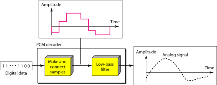
PCM Decoder
To recover an analog signal from a digitized signal we follow the following steps:
–We use a hold circuit that holds the amplitude value of a pulse till the next pulse arrives.
–We pass this signal through a low pass filter with a cutoff frequency that is equal to the highest frequency in the pre-sampled signal.
The higher the value of L, the less distorted a signal is recovered.
Components of a PCM Decoder
Advantages and Disadvantages of PCM

Delta PCM (DPCM)
Instead of using one bit to indicate positive and negative differences, we can use more bits -> quantization of the difference.
Each bit code is used to represent the value of the difference.
The more bits the more levels -> the higher the accuracy.
Delta Modulation
This scheme sends only the difference between pulses, if the pulse at time tn+1 is higher in amplitude value than the pulse at time tn, then a single bit, say a “1”, is used to indicate the positive value.
If the pulse is lower in value, resulting in a negative value, a “0” is used.
This scheme works well for small changes in signal values between samples.
If changes in amplitude are large, this will result in large errors.
Defination: Delta Modulation is a technique which provides a staircase approximation to an over-sampled version of the message signal (analog input).
Sampling is at a rate higher than the Nyquist rate – aims at increasing the correlation between adjacent samples; simplifies quantizing of the encoded signal

Delta Modulation Components

Delta Demodulation Components

ADAPTIVE DELTA MODULATION
Adaptive Delta Modulation, where the step size is made to vary with the input Signal.
- More efficient than PCM by removing the redundancies in the speech signal.
- Adjacent samples of a speech waveform are highly
correlated. - This means that the variance of the difference between adjacent speech amplitudes is much smaller than the variance of the speech signal itself.
ADPCM
1. Remove redundancies from speech signals
2. Assign available bits to encode non-redundant parts of speech signal in an efficient way
Standard PCM is at 64 kb/s – can be reduced to 32, 16, 8 or
even 4 kb/s
Price = proportionally increased complexity
— For same speech quality but Half the bit rate – Computational complexity is an order of magnitude higher
Allows encoding of speech at 32 kb/s – requires 4 bits per sample
Uses adaptive quantization and adaptive prediction
–adaptive quantization – uses a time-varying step Δ[n]. The step-size is varied to match the input signal σM2
φ is a constant; the other – estimate of the standard deviation – has to be computed continuously
- Instead of encoding the difference between adjacent samples, a linear predictor is used to predict the current sample.
- The difference between the predicted and actual sample called the prediction error is then encoded for transmission.
- Prediction is based on the knowledge of the autocorrelation properties of speech.
Comparison between PCM, Adaptive Delta Modulation and Differential Pulse Code Modulation

Pratik Kataria is currently learning Springboot and Hibernate.
Technologies known and worked on: C/C++, Java, Python, JavaScript, HTML, CSS, WordPress, Angular, Ionic, MongoDB, SQL and Android.
Softwares known and worked on: Adobe Photoshop, Adobe Illustrator and Adobe After Effects.